There is the shematic view:

 Hungarian version
The microcontroller is a complete computer that has only few periphery connecting with the world. These "computers" has a simple 8 bit CPU, they are working with few kBytes of program memory, few 100 Bytes of RAM (if it has any) and they operates with 1 - 10 MHz of clock frequency.
There are lots of microcontrollers developed by different manufacturers on the world,
but if we want to use them, we should use theirs own developing software and own burning
tools of the microcontroller. These can be so expensive.
For the Atmel AVR
microcontroller architecture there are several free developing utilities.
The official developping tool is Avrstudio that operates with M$ Windows.
But if I want to burn the developped software do I have to buy the official burning
tool for about 100 €? Hmmm...
There are developing tools for AVR architecture which are operating with UNIX operating systems, eg. tavrasm and avr-gcc. Hooray! The developping of microcode can move in a rut in UNIX environment. The task is only to burn it physically to the microcontroller...
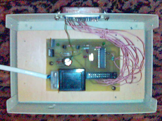
The hardware onsists of a simple supply voltage generator, a simple adapter circuit that can
communicate with the PC. The simplest way to realise the adapter circuit is using a
microcontroller. For this the AT90S1200
was choosen. That is fully compatible with AT90S2313 and ATtiny2313.
There is the shematic view:

The 8 data bits of the LPT port are all connected to the microcontroller to be burnt, and the first two bits of this data byte are also connected to the driver microcontroller. This way data sent to the parallel port of the PC is aimed either for the driver microcontroller or for the microcontroller to be burnt. The driver microcontroller always knows which byte is for itself and which byte is meant for the microcontroller to burn, and it gives control signals to the other IC only when the byte is a data, an address or a command byte for the chip to be programmed.
The role of IO pins can be changed easily from software, so the connection routing is only
optimalized for the simpler printed-circuit.
There is the image of printed-circuit:
avrburn_nyak-1.0.0.fig
avrburn_nyak-1.0.0.pdf
avrburn_nyak-vasalo-1.0.0.pdf(turned)
To help connecting parallel port pins to the hardware: parport.html
